Pages

Search This Blog

Sunday, December 14, 2014

Gas Cap Blowdown (GCBD)

Gas Cap Blowdown (GCBD) is a process of depressurizing the gas cap of a reservoir.

GCBD is applied to extract the gas available in the gas cap of a reservoir after full extraction of the oil reserves. After the operator is convinced that the remaining oil volume can not be commercially extracted, the pressure energy preserved in the gas cap is no longer required. Hence, it can be allowed to deplete or depressurize and in the process gas can be produced for sales or other applications.

GCBD is carried out especially in oil-rim or oil-sheet type reservoirs where oil is sandwiched between an aquifer and a gas cap. It is carried out in several stages as described below.

Stage-I: Stop pressure maintenance, that is, shut-down any gas and water injection wells, while keep producing the oil producers as normal.

Stage-II: Open-up the high GOR wells previously shut-down. Keep producing oil and gas from other existing wells. GOR will increase in all the wells and eventually they will all become gas wells.

Stage-III: The down-dip wells will be watered-out. Shut-down any watered out wells. The water-front will gradually move up the reservoir watering out the gas wells one by one. At the end, the crestal most well.

The life-cycle of an oil rim under-going GCBD is shown in the following series of figures. Abbreviations: OP=Oil Producer, GI=Gas Injector, HGOR=High Gas Oil Ratio, GOR=Gas-Oil-Ratio, GP=Gas Producer.

Figure-1: At the beginning of field life. 

Figure-2: In later stage of field life. 

Figure-3: At the end of oil producing phase. Decision time for GCBD.

Figure-4: Stage-I of GCBD started.

Figure-5: Stage-II of GCBD started.

Figure-6: Stage-III of GCBD.

Figure-7: At the end of GCBD process.

Sunday, November 30, 2014

Reserve Estimation

One of the main factors that determines the viability of an investment in an oil and gas field is the volume of the hydrocarbons present in it. In simple terms, we would like to invest to produce oil and gas, if only the money that can be generated by producing the hydrocarbon from that field generates profits. As typical investments in a field run into billions of dollars in terms of facilities and operation costs, it becomes imperative to have a good idea about the hydrocarbons present.

Initially, when we set out to develop a field, we do not have much idea about the reservoir and its characteristics viz. porosity, permeability, areal extent, thickness etc. As we continue to drill wells and develop the field, we get more and more data about the reservoir.

Correspondingly, at the beginning we have very little idea about the crude volume in place at the reservoir and so we employ some relatively simple and unsophisticated methods for determining the volume. These methods have a high degree of uncertainity associated with it. This means that there is a high probability that the volume which we have estimated from these methods may have a wide variance from the actual volume in the reservoir.  The methods employed at this stage are : Analogy and Volumetrics.

Later , as we have more data from the reservoir , we can employ more sophisticated and reliable methods for generating the volume of hydrocarbon. The results that we generate from these methods have a higher degree of certainity and we can expect the results to be closer to the actual values.The methods employed are : Decline Curve Analysis , Material Balance and Numerical Reservoir Simulation.


Friday, November 21, 2014

Decline Curve Analysis or DCA

As a reservoir is produced, after an initial peak and plateau period, the production rate starts to decline at certain rate. Analyzing this decline, a Reservoir Engineer can predict the Estimated Ultimate Recovery of the field. This technique is called DCA or Decline Curve Analysis.

While identifying the decline rate or decline trend, one needs to make sure the production is occurring at constant "operating conditions". For example, constant "bean size" in a producing well. 

The scope of analysis may be 
(a) an individual well or well-string
(b) a given reservoir zone
(c) a field 
(d) a bigger area or region
or even
(e) global

However, individual well-string or a given reservoir zone are commonly used or technically valid.

There are other kinds of 'trend analysis', e.g.
(a) Water-Oil-Ratio (WOR) vs. Cum Oil
(b) Gas-Oil-Ratio (GOR) vs. Cum. Oil

These are also used in conjunction with oil decline analysis to determine the economic life of the well or reservoir or the field in question.

For gas reservoir, a different approach, "p/Z-plot" is adopted. It will be discussed separately.

Monday, November 17, 2014

Decide your Reservoir Engineering tool wisely....

Providing timely and sound technical "advice" to the management is one of the primary jobs of a Reservoir Engineer. "Advice" is like a product that Reservoir Engineers generate to assist management take effective decisions. These decisions in turn effects the financial health of the company.

With the limited time and resources, it is very important to decide the correct tool to be used to generate the correct and timely "advice". In order to justify a bigger financial commitment by the investors, a more rigorous and robust technique is required. However, more the robust and rigorous technique is, more data / information is demanded by the technique. A simpler technique can be used to obtain results in shorter time using less amount of data; however, the results may not be as reliable as a more complex method would yield.

There is a time element to the equation. With longer investment of man-days, a better results might be obtained. However, capability of the technique; quality and quantity of data play a limiting role to the robustness of the result. 

Figure-1
Figure-1 attempts to typical time duration required to carry out different RE studies and a relative complexity of the result that can be achieved from these techniques. It compares (a) Decline Curve Analysis, (b) Material Balance, (c) Streamline Simulation, and (d) Finite Difference Simulation.

Reservoir Drive Mechanisms

Production of oil and gas from a hydrocarbon reservoir is simply a matter of supply of the energy that would allow the reservoir fluids to come up to the surface. Depending on some properties of reservoir viz. pressure , geology , PVT properties of the crude , each reservoir would have a different mechanism for energy supply.

The mechanisms for energy supply for production of oil and gas from the reservoir is what we commonly know as the Reservoir Drive Mechanism.

The most commonly observed Drive Mechanisms include :

  • Solution Gas Drive
  • Gas Cap Drive 
  • Water Drive 
  • Compaction Drive
  • Gravity Drainage
More than one drive mechanism can exist in a reservoir. However , one  is usually the dominant mechanism in the reservoir .

If we have an idea about the dominant drive mechanism in a reservoir , we can generate the expected recovery , production and pressure profiles of the reservoir.


Friday, November 14, 2014

Hydrocarbon Reservoir Types

Hydrocarbon Reservoirs can be classified in terms of how the fluid present changes due to change in pressure and temperature as it is brought out to the surface. 
  • Dry Gas Reservoir: The fluid present in the reservoir is in gaseous form and it remains in gaseous form as it is brought out to the surface.
  • Retrograde-Condensate Gas Reservoir: The fluid present in the reservoir is in gaseous form. However, part of it condenses into liquid form either in the reservoir itself or on it's way to the surface. What is produced is primarily gas with smaller quantities of liquid hydrocarbon.
  • Wet Gas Reservoir: The fluid present in the reservoir is primarily gas, but contains small amount of liquid. When produced, gas is produced along with small amount of liquid. 
  • Volatile Oil Reservoir: The fluid present in the reservoir is very light oil. Gas forms as it is brought to the surface. If produced oil is kept in an open container, it evaporates away.
  • Black Oil Reservoir: The fluid present in the reservoir is heavier oil. Some dissolved gas might be present. However, the produced oil is "dead", i.e., does not evaporates away if kept in an open container.

Sources:
  • http://www.informit.com/articles/article.aspx?p=2241145&seqNum=4
  • http://petrowiki.org/Natural_gas_properties

Wednesday, November 5, 2014

Gas Lift

As production from the reservoir continues,  gradually the energy of the reservoir depletes and it is no longer able to lift oil to the surface. At that point, Artificial Lift is employed which enables us to bring the oil from the depleted reservoir through the well to the surface. Approximately, 80% of the oil wells around the world are now on Artificial Lift and the most popular method employed is the Gas Lift.

In Gas Lift, a high pressure gas is injected into the well from the Casing - Tubing annulus. The injected gas reduces the  density of the fluid above the point of injection in the well. Because of the overall reduced density, the fluid exerts less pressure on the reservoir and flow from the reservoir into the well can continue.

Gas Lift System can broadly be classified into two main categories: 
  • Continuous Gas Lift
  • Intermittent Gas Lift
Continuous Gas Lift 

In this, gas is continuously injected into the well at the maximum possible depth, which depends on the injection pressure and the well depth. The  gas mixes with the produced well fluid and decreases its density and hence  the  pressure gradient of the mixture from the point of gas injection to the surface. The decreased  pressure gradient reduces the flowing Bottomhole Pressure (BHP) below the static BHP thereby creating a difference in pressure  that allows the reservoir fluid to flow into the wellbore. 

This is typically employed in wells with high production rate and high BHP.

Continuous Gas Lift

Intermittent Gas Lift

As the name suggests, gas is injected periodically into the wellbore which displaces the fluid which accumulates as a slug in the well. When the high pressure gas is injected into the well , it rapidly expands and this expansion pushes  the slug towards the surface. Because of the intermittent nature of the gas injection , the well produces less than a well with continuous gas lift. 

The intermittent gas-lift method typically is used on wells that have low production rates.
Intermittent Gas Lift

Sunday, November 2, 2014

Thermal EOR


Thermal recovery techniques principally targets crude oil with very high density  ( < 20 deg API ) which cannot flow on its own. These methods raise the temperature of the reservoir which in turn reduces the viscosity of the crude and breaks the larger crude oil molecules into smaller molecules. The heat also reduces the surface tension and improves the overall mobility of the crude.

Some of the major techniques that are employed in the industry :
  • Cyclic Steam Stimulation
  • Steam Flood
  • In-Situ Combustion

Thursday, October 30, 2014

Oil Companies

The oil companies or agencies involved in the oil industry can be broadly classified into 3 groups:
  1. Host Authorities
  2. Operating Company or Operators
  3. Service Providers

Tuesday, October 28, 2014

What is Streamline Simulation?

Streamline simulation technique simplifies the conventional finite difference 3D simulation (FD) into a number of 1D problems by assuming some streamlines or pipes that transport the oil molecules from high pressure zone to low pressure zone. They depict the actual flow-path of fluid molecules within the reservoir.

Source: Schlumberger
Because of its simplicity, large reservoir model can be subjected to such simulation techniques with limited computer resources. Or, large number of models or realizations can be analyzed within short period of time. The technique may not give a robust result that can be fully trusted for large scale economic investment decisions. (We have to rely on more reliable and proven techniques of FD simulation). However, it is very good tool for a number of purposes.

Sunday, August 24, 2014

Pressure Transient Analysis

Pressure Transient Analysis (PTA) is simply the measurements the change of Bottom Hole Pressure (BHP) of a well as it is opened or closed. 

In a production well,  as flow-valves is opened and fluids starts to flow, BHP decreases. Measurements of pressure drop in such a well is called "Pressure Draw-Down Test". On the other hand, when the well is closed, BHP increases. Measurements of building up of pressure of such a well is called "Pressure Build-Up Test".

In an injection well, as injection starts BHP increases. Measurements of pressure building up in such a well is called "Pressure Build-Up (Injection) Test". On the other hand, when the well is closed, injection stops and BHP decreases. Measurements of pressure fall in such a well is called "Pressure/Injection Fall-Off Test".

Wednesday, August 20, 2014

What is 4D siesmic ?

4D seismic survey is simply a series of three dimensional (3D) seismic surveys over the same area of interest at different times. Here "time" is considered as the 4th dimension.

As a field produces oil or gas, the reservoir fluid distribution and pressure changes. This variation is reflected in seismic surveys,. The difference of surveys taken before and after production can us a clearer picture of remaining oil/gas un-swept or remained trapped and help engineers plan/redesign the depletion strategy like new infill drilling, injection optimization etc.

Monday, August 18, 2014

Recovery Factor

Recovery Factor is the amount of hydrocarbon that can be recovered or produced from a reservoir per unit volume of original in place. Mathematically, it can be written as follows:

RF = EUR / STOIIP *100 % for oil
RF = EUR / GIIP * 100 % for gas

where,
RF = Recovery Factor
EUR = Estimated Ultimate Recovery
STOIIP = Stock Tank Oil Originally in Place
GIIP = Gas Initially In Place

Sunday, August 17, 2014

Petroleum Engineering - Scopes & Future

From an Indian student's perspective:

Scope-wise, I must admit, it’s quite narrow…. only the petroleum industry (unless, he diversifies into IT/MBA/Civil Service etc.) In India, currently there are a number of institutes offering B.E./B.Tech in Petroleum Engineering; but no. of jobs for fresher’s seems to be not enough. For first few months after graduation, sometimes, a fresher may have to do some job hunting. Jobs for Indians outside India like in the middle-east or far-east is actually very good. However, everywhere, they want relevant experiences of 7+ years; almost rare to zero scopes for a fresher.

However, once ice-broken into the Petroleum Industry, one can have a wide range of options from drilling to production to reservoir to facilities.  He/she do faces competitions from candidates of other disciplines like mechanical, civil, chemical etc especially in drilling, production and facilities. However, as Petroleum Engineers are especially trained for the oil industry itself, it is easy to excel. One can command a highly paid, technically satisfying career in the industry.

Future-wise, I do not see any threat in the foreseeable future. As long as petroleum is not significantly replaced by other sources of energy, petroleum engineers will be in demand. Rather, as natural resources shrinks and demands expands, I foresee demands growing exponentially --- more so for expertise in areas like EOR, maginal fields and unconventional reserves.

In conclusion, I strongly recommend one to pursue petroleum engineer as a career.

Friday, August 15, 2014

Material Balance or Tank Model

As the name implies, this analysis revolves around "materials" flowing in and out of box. The reservoir is assumed to be a box or tank and the oil, water & gas or any other fluids entering (e.g. due to water influx, injection etc) and leaving the tank (e.g. production) are modeled. Expansion or shrinkage of these fluids and compaction of rocks in response to change in pressure are also considered. The pressure response produced by the model is compared to the actual / observed pressure responses. The model parameters are adjusted till a satisfactory response is obtained. Some very significant understanding of the reservoir like STOIIP, Aquifer Strength etc can be obtained from this analysis. 

If the case demands, multiple connected tanks are also assumed. In some analysis, wells are added.

Wednesday, August 13, 2014

Water / Aquifer Drive

It is one of the most common natural drive mechanism present in many oil and gas reservoir. Water bodies or aquifer below or around a reserve exert a force on it. When a well is drilled into the reservoir and opened to the atmosphere (or lower pressure), oil or gas starts flowing naturally to the surface at considerable pressure due to the force exerted by the aquifer. 

In such reservoir, pressure is maintained even after a large quantity of fluid is produced. Therefore, the recovery efficiency or recovery factor can go up to 40-50%. However, if proper reservoir management is not followed, water cut may increase considerably and lower the recovery.


Gravity Drainage Drive

It is one of the natural drainage mechanism where due to density differences, fluids tends to segregate out in the reservoir. For example, during production gas coming out of solution moves up and accumulate at the top of the reservoir due to gravity segregation, pushing more of the underlying oil towards the producing well.

Another name of this mechanism is Gravity Segregation.

Almost always, this mechanism works in conjunction with another drive mechanism.

Bubble Maps

Figure-1
Bubble Map is a very common and conventional tool used by Reservoir Engineers to visually represent amount of fluids extracted by the wells of a reservoir.
Figure-2

Figure-3
The amount of fluids produced is represented as a circle with the center located at the well location and a radius corresponding to the fluids produced from the well. A number of different parameters and combinations are plotted in a bubble map for different kinds of interpretations. Some common combinations are:
  • Cumulative Oil (Figure-1)
  • Cumulative Liquid
  • Cumulative/Current Oil and Water (as Pie Chart to show the proportions of oil and water, Figure-2)
  • Estimated Ultimate Recovery and Cumulative Oil (as co-centric circles to show the amount of oil produced out of the EUR, Figure-3)

What is "Blow-Out" ?

The hydrocarbon reservoirs often contains oil and gas naturally in high pressure. A lots of precautions needs to be taken to contain the high pressure in designing a oil or gas well and similar precautions are taken during drilling and then producing the well.

However, due to equipment failure or human error, if the flow of reservoir fluids to the surface is becomes uncontrollable, it is called "blow-out". Inflammable fluid (oil+gas) often catches fire and damages rigs and other surface equipment.

During drilling, often gust of high pressured fluids enter the well. The phenomena is called "kick". Controlling the kicks are special skills the drillers are expected to learn and implement. 

BOP or "Blow Out Preventor"s are special equipment used during drilling and work-over to prevent such events.


Tuesday, August 12, 2014

What is MEOR ?

MEOR or Microbial Enhanced Oil Recovery is an enhanced oil recovery method, where a carefully selected microbes are nurtured in the reservoir. The microbes "eat" the heavy components of the crude oil and convert them into higher components so that they can move easily from the reservoir to the well and then up to the surface. The microbes also release chemicals such as surfactants, CO2 etc that also assist in oil recovery.

Nutrients and oxygen must be supplied to the reservoir for the microbes to flourish and give the desired results. Hence, it is often difficult to implement the process across the reservoir.

Globally, this method seems to have limited success. 

Monday, August 11, 2014

What is Foam Injection?

Foam Injection is a method of Enhanced Oil Recovery, whereby "foam" are either injected or generated in the reservoir to improve the oil recovery. "Foam"s are very small bubbles of gas inside a liquid. 

Foam is as light as gas, but has higher viscosity. This lowers the mobility ratio of the injected phase and give rise to a more favorable mobility ratio. Foam can be injected with an existing gas injection setup.

Saturday, August 9, 2014

Why flare?

People often question why do the oil companies flare "valuable fuel" non-stop 24x7 for months and years. Can`t they use or sale those fuel instead of "wasting" by flaring them up?

It's a very valid question !!

Let me try to answer in simple language. When oil is produced, certain amounts of gas also comes out from the reservoir. Depending on the proportions of oil and gas present in the reservoir and the production conditions, the amount of gas may vary. However, production of these "associated gas" is inevitable. 

We can have buyers for oil in the immediate vicinity or if need arises, we can also transport them by laying pipelines or by tankers to a distant market. However, demands or markets for gas may not be as big as that of oil. Moreover, it is very difficult and costly to transport gas to a far flung market. The oil companies do their best to utilize the produced associated gas by using it internally as fuel, re-injecting back into the reservoir where possible or required. After all these, the excess gas that has no buyer needs to be disposed off. 

If they release the excess inflammable gas into the atmosphere, it is a safety issue as well as environmental concern. Therefore, they dispose by flaring them so that safety is not compromised and environmental damage is minimized.

I hope, the article will help understand the why the oil companies are forced to flare the excess gas.

Friday, August 8, 2014

What is Relative Permeability ?

The flow of one fluid is restricted by the presence of another fluid through the narrow connected pore spaces of a rock system. The phenomena is quantified by a parameter called "Relative Permeability", which is defined as the ratio of the permeability of fluid X in presence of fluid Y to the permeability of fluid X alone in a rock system. 
Figure-1: When only one fluid is present, it can flow easily with relatively less restrictions. Here the red-colored humanoids are representing oil molecules "running" through the connected pore spaces.

What is MWD & LWD ?

MWD stands for Measurements While Drilling.
LWD stands for Logging While Drilling.

As a well is drilled to a subsurface target, some instruments are attached to drilling string just above the drilling bit. The MWD tools measure the well trajectory parameters like inclination, azimuth etc, while LWD tools measure rock properties like Gamma Ray, Neutron & Sonic Density etc.

In modern highly complicated reservoirs, these tools play vital roles in steering the well along the most favorable reservoir body. It also saves time and money eliminating need for wireline logs and round trips of the drilling bit. 

Another very interesting aspects of these tools is that they communicate with the engineer sitting on the surface via mud-telemetry, that is, they uses pulses in the mud or the fluid system present inside the drill string to send data to the surface and also to receive instructions from the surface.


What is Viscosity ?

In laymen's language, viscosity is the measure of how thick a fluid is. A more viscous material will flow slowly compared to a less viscous material. The following statements makes the idea of viscosity even clearer.
  • Water is less viscous than molasses.
The common unit used for viscosity is centipoise, denoted by "cp".

Viscosity is the result of molecules of the system interacting with each other. More strongly they interact, less freely they can move, causing higher viscosity. The amount of molecular interactions, in turn, is caused by types of molecules, energy they possess and proximity of the molecules.

For a given temperature, viscosity of crude oil varies with pressure. Above bubble point pressure, viscosity increases as pressure increases. Due to pressure the molecules tend to come closer increasing interactions among them. This results in higher viscosity.

Packed Hall = High Pressure 
= Difficult to move around
= High Viscosity
Sparse Hall = Low Pressure
= Easy to move around 
= Low Viscosity


One the other hand, below bubble point pressure, viscosity increases as pressure decreases. At lower pressure, the lighter gas molecules escapes from the system, allowing the more heavier molecules to interact with each. This results in higher viscosity.


What is Connate Water ?

Connate Water simply means the original water present in a subsurface reservoir. They can be called the "fossil water" as they are entrapped inside the subsurface for millions of years.

The proportion and the chemistry of connate water play a significant role how the reservoir will behave as we start interacting with them while starting commercial oil and/or gas production.

Thursday, August 7, 2014

Workover / Well Intervention

The Workover / Well Intervention refers to maintenance or corrective measures conducted on an oil or gas producing well or injection well by first shut-in the well and then lowering various tools to carry out the task.
Some of the common workover jobs are:

  • Zone Shift 
  • Reperforation
  • A/L Installations
  • Acid Job
  • Water Shut-Off Job

What is GOR ?

GOR stands for Gas-Oil-Ratio.

It is very common way of expressing amount of gas produced while producing an oil well. Common unit is MSCF/bbl.

Just like we have dissolved gas in a pressurized coke bottle, some amount of gas  remains in solution in the crude oil at reservoir conditions. The ratio of dissolved gas or "solution gas" per unit volume of oil is called Solution Gas-Oil-Ratio. It is often denoted by Rs.

However, the well produces not only solution gas, but also some amount of free gas. The total gas produced per unit volume of oil is called Produced Gas-Oil-Ratio and is denoted by Rp.

Mathematically,
Rp = Rs + Free Gas


What is WAG ?

WAG stands for "Water Alternative Gas".
It is an improved oil recovery (IOR) process where water and gas are injected one after another from the same injector wells. For example, water is injected for 3 months followed by gas injected for 3 months and the cycle repeats over and over again. This cycle may be optimized and can vary from weeks to months. 
The process is found to give incremental benefit in terms of ultimate recovery over only water or gas injection.

You may read more details from these sites:

What is EOR ?

EOR stands for Enhanced Oil Recovery.

It is a process where oil production is attempted to increase or the ultimate recovery is maximized by injecting an agent not naturally present in the reservoir, such as various kinds of chemicals, microbes or stream etc. Broadly EOR processes can be classified as follows:
1) Thermal Processes
  • Steam Injection
  • In-Situ Combustion
2) Chemical Processes
3) WAG (Water Alternating Gas Injection)


Wednesday, August 6, 2014

What is FVF ?

FVF stands for formation volume factor. It is the amount of oil at reservoir condition that can produce 1 unit volume of oil in stock tank or surface conditions. Mathematically,
FVF = Reservoir Volume of Oil / Stock Tank Volume of Oil.
In barrels, the unit is RB/STB ( Reservoir Barrels / Stock Tank Barrels)
It is often denoted by Bo.


Tuesday, August 5, 2014

Who works with Reservoir Engineers?

Reservoir Engineers can not work in isolation. He/she needs support from a wide range of people of different backgrounds. Similarly, the output or work generated by a Reservoir Engineer might be used by another group of diversed people. In this article, an attempt will be made to describe some of these people working hand-in-hand with Reservoir Engineers.

Monday, August 4, 2014

What is Polymer Flooding ?


In simple language, polymer flooding in a reservoir involves injection of water mixed with polymer increase it's viscosity and thereby reduce it's mobility. 

In a heterogeneous reservoir, relatively more mobile water by-passes a viscous oil, creating an unstable water front and leaving behind a huge amount of unswept  oil. Polymer is added to the injected water to increase it viscosity and it helps to establish a stable water front and improve the sweep efficiency of the reservoir. 
Figure-1
Figure-2
In Figure 1, a situation where more mobile water is "finger" towards the producer faster is shown. On the other hand, Figure-2 shows a polymer mixed water injection, where the water front is relatively stable and the fingering effect is less.

Sunday, August 3, 2014

What is STOIIP or OOIP ?

The full form of these two abbreviations are as follows:

  • STOIIP = Stock Tank Oil Initially In Place
  • OOIP = Original Oil In Place, or
  • STOOIP = Stock Tank Original Oil In Place

All of the above, essentially mean the volume of oil originally or initially present in a hydrocarbon reservoir expressed in equivalent volume that it would occupy in a stock tank at standard temperature and pressure.

Mathematically, it is expressed as:

STOIIP = BV *Ï• * (1-Swi) / Bo

where,
BV = Bulk Volume of the Reservoir
Ï• = Porosity (need to be Effective Porosity)
Swi = Initial Water Saturation
Bo = Formation Volume Factor

Capillary Pressure

Due to interfacial tension (IFT), a fluid experiences a force of pressure known as "Capillary Pressure" through the narrow capillaries of a porous medium and rises up or down from the free fluid level. In Figure-1, the left side of figure shows water rising above the Free Water Level (FWL) differently in capillary tubes of different diameters, whereas the right side of the figure shows the same phenomena in a porous medium with different pore sizes.
Figure-1
Capillary Pressure is often observed in oil-water hydrocarbon system with a varied thickness of a "Transition Zone". In some situations, the entire reserve may be within the "Transition Zone". 


What is Wettability?

Another very important parameter that a Reservoir Engineer is concerned about is "wettability". It is measure of how a surface is soaked or wet in a given fluid in presence of another fluid. It is measured by the angle that a droplet of the liquid in question would make to the given surface. The concept is illustrated in the following figure-1

Figure-1

Saturday, August 2, 2014

Hydrocarbon Reservoir

A hydrocarbon reservoir is a subsurface natural storage of hydrocarbon fluids such as crude oil and natural gas. Generally, these natural storages are sedimentary rocks like sandstone or limestone. In rare occasions, igneous rocks like granite can also store hydrocarbon naturally in some very special conditions.

In order to form a hydrocarbon reservoir, 3 basic conditions must fulfilled:

  1. Presence of "Source Rock". A source where hydrocarbon formed in the vicinity of the reservoir.
  2. Presence of "Cap Rock". These must be a "cap" or impermeable rock to prevent the hydrocarbon from escaping.
  3. Presence of porous medium. For the hydrocarbon to reside, the reservoir rock must contain empty spaces called pore spaces. These may be in-matrix pores or fractures.

What is Permeability ?

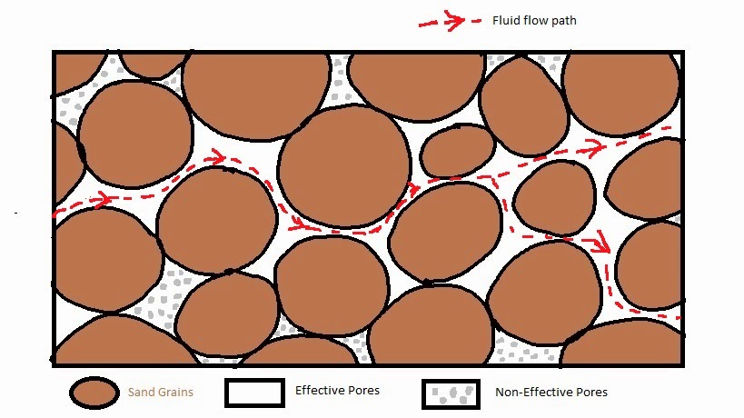
"Permeability" is measure of a porous rock system how easily it allows fluids to move through it. The common unit of permeability is "milli darcy", represented by "mD". Figure-1 illustrates the fluid flow path through the effective pore spaces.
Figure-1
A rock can be highly porous, that is have high porosity, but may have low permeability or vice-verse.

"Absolute Permeability" is the permeability in a porous medium as such sand stone for a single fluid like oil or water.

"Effective Permeability" is the permeability of a given fluid (such as oil or water or gas)  in presence of another fluid in a porous medium.

"Relative Permeability" is the ratio of "Effective Permeability" for a given fluid in presence of another fluid to the absolute permeability of the porous medium.

What is Porosity

"Porosity" is the measure of pore spaces of a porous media. Mathematically,
Porosity = (Bulk Volume - Matrix Volume) / Bulk Volume = Pore Volume / Bulk Volume

where
Bulk Volume = the total volume occupied by a given rock body in 3D
Matrix Volume = the volume occupied by the rock grains
Pore Volume = the volume occupied by the space in between the rock grains.
Figure-1

In Figure-1 the outer black rectangle represents the "Bulk Volume", "Matrix Volume" or sand grains and between the  "Pore Spaces" or "Pore Volume" are represented in brown and white color respectively.

It is represented by the Greek letter Ï• (phi).

"Total Porosity" is the ratio of total pore space irrespective of weather they are connect or not to the bulk volume. "Effective Porosity" is the ratio of connected pore spaces to the bulk volume. This is the actual pore space from where fluid can flow to the producing wells (Figure-2).

Figure-2

Friday, August 1, 2014

What is PVT Analysis?

An important task that the Reservoir Engineers carries out is Fluid Characterization or PVT (Pressure-Volume-Temperature) Analysis. The objective is to define the hydrocarbon fluid system present in a given reservoir and model it a computer program. A number of experiments are conducted on carefully collected fluid samples and a mathematical equation is calibrated to represent them. The equations known as "Equation of State" (EOS), are then used to predict the behavior of the fluid in different reservoir and surface pressure-temperature conditions.

What is Artificial Lift ?

When the reservoir pressure is not sufficient to lift hydrocarbon from the bottom of the well to the surface, the lift mechanism employed to lift them to the surface and transport to the nearest collecting or separating facilities is called "Artificial Lift". The following list gives some commonly used artificial lift systems:

  • Gas Lift (GL)
  • Rod Pump / Sucker Rod Pump
  • Electrical Submersible Pump (ESP)
  • Hydraulic Pump
  • Progressing Cavity Pump (PCP)

What is Drive Mechanism?

Natural "Drive Mechanism" of a hydrocarbon reservoir is the natural energy available to push fluid from different parts of the reservoir to the producing well. There are a number of drive mechanisms identified. Often, more than one mechanism act simultaneously on a reservoir. The following is a list of most common drive mechanism:

  • Aquifer Drive / Water Influx
  • Gas Cap Expansion Drive
  • Solution Gas Drive
  • Gravity Drainage

What is Water Flooding ?

"Water Flooding" or "Water Injection" is an improved oil recovery method, where water is injected at some carefully selected located parts of  the hydrocarbon reservoir to improve hydrocarbon recovery either by "pressure maintenance" or by improved "sweeping" of the reservoir.

What is Flow Simulation?

"Flow Simulation" is a technique used by Reservoir Engineers to understand the flow behavior of a hydrocarbon reservoir. It uses a special computer software to mathematically represent the reservoir, the wells penetrating it and then they study the change of different fluids concentrations and pressure through out the reservoir as fluid is withdrawn and introduced from/to it.

"Flow Simulation" involves several steps, namely...
  • Model Construction
  • Model Initialization
  • History Matching
  • Prediction or Forecasting

How do Reservoir Engineers work?

Reservoir Engineers use a wide range of tools to do their jobs. Some of the commonly used techniques are listed below:
  • Classical Reservoir Engineering
    • Material Balance
    • Decline Curve Analysis
    • Nodal Analysis
    • Pressure Transient Analysis
    • Fractional Flow Curve Methods (1-D displacement by Buckley-Leverett, Deitz method)
    • PVT Analysis 
    • SCAL Analysis
    • Uncertainty Analysis
    • Petroleum Economic Analysis
  • Flow Simulation
    • Finite Difference Flow Simulation 
    • Streamline Simulation
    • Black Oil / Compositional Simulation

Who can become a Reservoir Engineer ?

Generally who studied "Petroleum Engineering" as his/her major discipline in undergraduate or gradate level becomes "Reservoir Engineer". Frequently, students majoring in Geoscience, Chemical Engineering are also seen engaged as "Reservoir Engineer"s. Students with other backgrounds, like mathematics, physics, mechanical or process engineering are also sometimes  seen as Reservoir Engineers. However, most of the time they undergo post graduate level training in Reservoir Engineering.

What is Reservoir Engineering?

"Reservoir Engineering" refers to the engineering discipline that deals with understanding the flow of fluids like gas, oil and water through the pore spaces of underground rocks and techniques to recover them in an economically efficient manner.

Thursday, July 31, 2014

Who is a Reservoir Engineer ?

A "Reservoir Engineer" is a professional who studies the subsurface fluid dynamics of a hydrocarbon reservoir. By the studying so, he/she attempts to

  • Estimate the quantities of recoverable hydrocarbon reserves.
  • Device the best field development plan (FDP) to exploit the reserve efficiently.
  • Predict the behavior of the field as it produces.
  • Maximize the value of the hydrocarbon resources.